

Amtec Guide to Coating Failures & Coating Breakdown
Introduction to Paint Problems.
There are many different types of coating failure, most of these result in paint or coating detachment. This sort paint failures guide describes the most common paint breakdown types and failures. Often the failure takes place for a combination of reasons that require an expert eye. Amtec offer a free initial e-mail or telephone consultation via the contact details above. You may even send photographs for examination.
Blistering
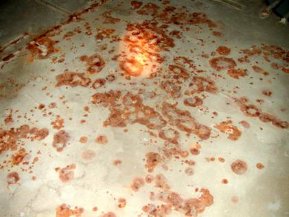
Blisters often take the form of clusters (or Rashes) of liquid filled, hemispherical bubbles at the paint/metal interface, although blisters can form between layers of paint, these are less common.
Typical blister rashes are shown in photographs 1 and 2. In order to give a sense of scale, a small notebook has been included in the latter figure.

Photograph 1. Blister rash at an area of localised contamination.

Photograph 2. Blister rash.
Blisters either originate from ionic contamination on the substrate prior to coating or are due to soluble material leaching out from the coating itself and migrating to the interface with the substrate. Water will always migrate through the film driven by osmosis and when the osmotic pressure within the blister balances the coating adhesion around its circumference, the blister ceases to grow.
Some Blisters can also be associated with areas of corrosion or sacrificial anodes. In this instance, their growth is driven electrochemically driven and complex rules govern their eventual size.
Commonly, blisters do not show corroded material underneath (due to the highly alkaline blister fluid) and are of concern only in areas where they can be broken mechanically e.g. by the action of water or foot traffic.
When blisters occur late on in the lifetime of the coating they may indicate immanent serious failure - coating barrier properties measurements can sort this out - for more details on this contact Amtec.
Through Film Breakdown.
Through film breakdown most commonly occurs due to insufficient coverage or low film thickness (low DFT or dry film thickness). It is one of the most common paint failures & takes the form of rust spotting. Sometimes it happens when coats have been missed. In marine applications it can occur in the ullage space at the top of ballast tanks and tends to be common the under deck plating. A typical example is shown in photograph 3. The coating breakdown shown is in the later stages of development, where the rust spots have grown due the warm and humid conditions found in these areas.

Photograph 3. Through film breakdown.
Through film breakdown usually occurs first on the upper surfaces of longitudinal stiffeners (photograph 4) and on stringer decks (photograph 7-3), where residual water remains on both surfaces for longer periods after the tank is first emptied.

Photograph 4. Corrosion spots on longitudinal stiffener.
Photograph 5. Corrosion spots on stringer deck.
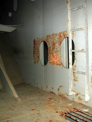
Edge breakdown
One of the areas to exhibit early coating breakdown is the edge of stiffeners (photograph 6) and around cut outs (photograph 7), which frequently fail through edge breakdown mechanisms.

Photograph 6. Coating breakdown on stiffener edge.

Photograph 7. Coating breakdown around cut out.
Often, special care is taken with the coating process in these areas. Edges can be ground smooth and stripe coats of paint applied by hand. Surface tension effects in the wet film, high coating velocity during spraying and poor local surface preparation are common caused of edge breakdown.
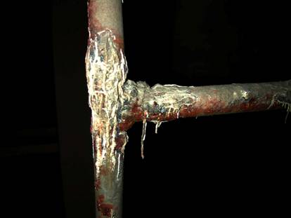
Weld Corrosion
Welds are susceptible to enhanced localised coating breakdown in the same manner as edges. Commonly, two types of weld corrosion occur. The first is illustrated in photograph 8, where corrosion initiates on either side of the weld bead in the area associated with oxide build up from the welding process.

Photograph 8. Corrosion around weld.
The second type of weld coating failure occurs much closer to the weld and is associated with poor surface cleanliness prior to coating. An example is given as photograph 9.

Photograph 9. Corrosion at weld.
Over thickness at the edges of the weld bead is also a contributing factor to weld corrosion. Weld spatter, (which takes the form of small beads of metal close to the weld) can cause micro-blistering if over coated.
Calcareous Deposit Induced Coating Failures
The presence of sacrificial anodes in ballast tanks induces the formation of hydroxyl ions at the coating/metal interface – which has the result of inhibiting or preventing corrosion from occurring beneath the coating. A side effect is that a white, chalky material (called calcareous deposit) forms beneath the coating.
The calcareous deposit originates partially from the reaction of carbon dioxide with the hydroxyl ions and partly as the result of semi-soluble carbonates being deposited from the sea water.
When the cathodic protection system is working well, the volume of the deposits is just sufficient to fill any cracks in the damaged area (photograph 10).

Photograph 10. Well performing cathodic protection system, with tight calcareous deposits.
When the anodes are overworked, then the voluminous deposits forming beneath the coating can lever it off the steel, as shown in photograph 11.
Photograph 11. Voluminous calcareous deposits.
Poor Surface Preparation
The most common cause of coating failure is poor surface preparation. When the film is in good condition at thicknesses of greater than 250mm, micro-blistering results. However, when the coating is either poorly applied or too thin, then failures of the type shown in photograph 12 tend to occur. This is typically extensive corrosion breakthrough occurring in localised, clustered areas.
Photograph 12. Example of poor surface preparation prior to coating.
Reverse Impact Damage
Reverse impact damage occurs on the inside of ballast tanks due to a sharp, high intensity impact from the outside of the tank. It is extremely common in bulk carriers, particularly on the hopper sides due to the action of grabs. The underside of the double bottom also receives many reverse impacts from grabs and bulldozers.
A typical example is shown in photograph 13, which illustrates the shatter patterns that result from the coating failing in a brittle manner.

Photograph 13. Reverse impact from grab causing brittle coating to shatter.
Reverse impact damage is also common in the shell plating, especially around tug contact areas and in the forepeak tank as a result of collisions with floating objects (photograph 14). This type of reverse impact damage are usually slower and result in distortion of the coating, which in turn leads to through film corrosion at the damaged site.
Photograph 14. Reverse impact from external collision.
Mud Cracking
Mud cracking of coatings takes the form shown in photograph 15.

Photograph 15. Typical mud cracking in thick coating.
Cracks in a typical pattern extend down from the surface of the coating and can reach the coating/metal interface. Mud cracking is generally a result of either a very high build up of coating or can be due to excessive thinning in conjunction with thick films. Often the interface with the steel is weakened and corrosion quickly initiates in the cracks.
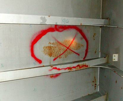
Stress Related Coating Failures
Corrosion can initiate at heavily stressed areas within tanks. Stress related coating failures can be recognized by their location or by the presence of the repetition of the same failure in the same place along the length of a structure, as shown in photograph 16.

Photograph 16. Stress induced coating failure.
Often stress related failures can initiate at cut outs as shown in photograph 17 or at the toes of welds as shown in photograph 18.

Photograph 17. Stress corrosion at cut outs.

Photograph 18. Stress induced corrosion at toes of welds.
Both stress and strain are causes of the coating failure. Stress concentrations can cause local anodic areas to develop, which then concentrates corrosion at that location. Strain can lead to cracking and disbonding of the coating, due to differences in mechanical properties between the coating and the underlying steel. Coating cracking due to stress is serious & requires expert advise.